The Mission 777 Power Amplifier
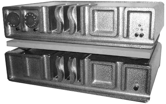
In 1982 the Mission 776-777 pre/power amplifier combination replaced the original 771/772 system. The 777 broke with Mission tradition by using paralleled complementary FET output devices instead of the usual bipolar transistors. This amplifier was well regarded for its sound; less so for its rather brutal looks and whilst innovative in many ways it had the great limitation that it didn't work well with pre-amplifiers other than the Mission 776. The reason for this was the fact that the 777 was a shunt feedback dc coupled design so there were no capacitors in the direct signal path. This mean't that there could be the problem of a dc 'offset' voltage appearing across the loudspeakers. This dc voltage was minimised by careful selection of several resistors in the factory but the setting assumed that the output resistance of the pre-amplifier would be that of the 776 design. Install a different pre-amp. and you could have unacceptable voltages across the loudspeakers.
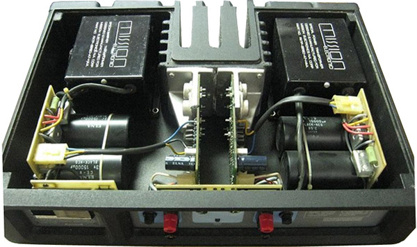
 The 777 was revised in 1983 as the 777BU model and largely discontinued in 1984 when the smaller Cyrus 778 amplifier was launched. It was a double mono unit with two amplifiers and two power supplies in the one case following the format of the earlier 772. The transformers were big 300VA "EI" types (not toroids) and the reservoir capacitors were ELNA Hi-Grade Lytics, 8x 15.000µF/63V, The output MOSFETs were Hitachi 2SJ50/2SK135s (alternatively 2SJ55/2SK175 or 2SJ56/2S176). The 777 was revised in 1983 as the 777BU model and largely discontinued in 1984 when the smaller Cyrus 778 amplifier was launched. It was a double mono unit with two amplifiers and two power supplies in the one case following the format of the earlier 772. The transformers were big 300VA "EI" types (not toroids) and the reservoir capacitors were ELNA Hi-Grade Lytics, 8x 15.000µF/63V, The output MOSFETs were Hitachi 2SJ50/2SK135s (alternatively 2SJ55/2SK175 or 2SJ56/2S176).
The output was rated at 100 wpc into 8 ohms and about 250 watts into 2 ohms was achieved on a good day. The frequency response was DC-400 kHz +0/-3dB. It retailed for £750.00 which was considered to be expensive at the time.
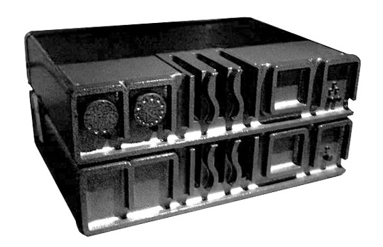
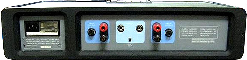 The rather brutal cast aluminium cases also formed the heatsink in the case of the power amplifier although it was rather wasted on the battery powered 776 pre-amplifier. As originally conceived the 776 had a Balance control on the rear panel but this degraded the sound due to the long signal paths and so it was disconnected. Some earlier production models were sold with the Balance control fitted but disconnected. The 777 power amplifier also had a soft-clip feature whose history went back to the Cambridge Audio Classic One amplifier of some years previously. Again this feature didn't really improve the sound and it was also disconnected although it still appeared on the rear panel. The rather brutal cast aluminium cases also formed the heatsink in the case of the power amplifier although it was rather wasted on the battery powered 776 pre-amplifier. As originally conceived the 776 had a Balance control on the rear panel but this degraded the sound due to the long signal paths and so it was disconnected. Some earlier production models were sold with the Balance control fitted but disconnected. The 777 power amplifier also had a soft-clip feature whose history went back to the Cambridge Audio Classic One amplifier of some years previously. Again this feature didn't really improve the sound and it was also disconnected although it still appeared on the rear panel.
 The 777 wired the output speaker fuse inside the negative feedback loop to minimise its effect upon the sound. This was a feature first appeared in the 772 amplifier and which I carried forward and subsequently used in the Acoustic Research integrated amplifier and the Cambridge Audio P35 amplifier. Despite the high price this amplifier can be seen to lack the constructional quality and massive over-engineering of the earlier Mission 772 amplifier. The 777 wired the output speaker fuse inside the negative feedback loop to minimise its effect upon the sound. This was a feature first appeared in the 772 amplifier and which I carried forward and subsequently used in the Acoustic Research integrated amplifier and the Cambridge Audio P35 amplifier. Despite the high price this amplifier can be seen to lack the constructional quality and massive over-engineering of the earlier Mission 772 amplifier.
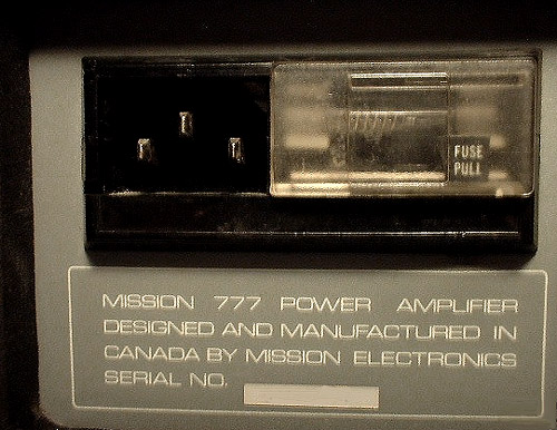 A small number of the 776/777 were assembled in Canada using sub-assembly parts from the UK as Mission was starting to sell loudspeakers sucessfully in that market and, indeed, was planning to set up a loudspeaker factory. A small number of the 776/777 were assembled in Canada using sub-assembly parts from the UK as Mission was starting to sell loudspeakers sucessfully in that market and, indeed, was planning to set up a loudspeaker factory.
 It is difficult to find service information on this amplifier so I've drawn up a simplified circuit schematic as best as I remember it, plus some design notes. There aren't many of these amplifiers around now but hopefully one or two of them will be kept running for a while longer yet. It is difficult to find service information on this amplifier so I've drawn up a simplified circuit schematic as best as I remember it, plus some design notes. There aren't many of these amplifiers around now but hopefully one or two of them will be kept running for a while longer yet.
Downloads <click on the logo to download> |
 Simplified Circuit Schematic for the Mission 777 Simplified Circuit Schematic for the Mission 777
|
A few design notes on the Mission 777 power amplifier PENDING
|
|